

We should all probably be segmenting our home networks, but why? With the prevalence of IoT (Internet of Things) devices, home automation, and internet connected security cameras, the exposure to external threats is ever expanding.
Whether this is your Alexa, Google Home, Nest devices, your refrigerator, coffee maker, security camera, or other devices that talk to external services, you just never know where that traffic is going, or whether that fridge you bought 6 years ago is still getting firmware updates and security patches. Isolating these devices from your computers and smart phones can be an excellent way to reduce the impact of potential threats from bad actors.
So how do we accomplish this segmentation? VLANs, Firewalls, and routers. Let's start with the concept of VLANs.
VLANs (Virtual Local Area Networks) allow you to create multiple networks for your devices to operate on and isolate traffic from one another.
A Deeper Dive on VLANs
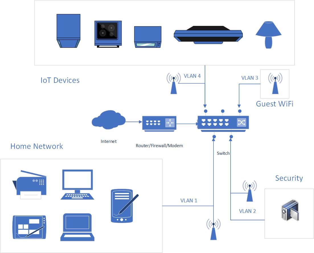
So in this example diagram we see that network traffic is being segmented into 4 distinct areas. Our home network that our own trusted devices live in, the security network, guest WiFi, and our IoT devices.
In your scenario, your Router/Firewall/Modem may also be your switch. You'll also notice that there are 4 distinct wireless access points depicted in this diagram, however it's possible that you will only need one, and it could even be your Router/Firewall/Modem as well.
Let's take a look at how all of those access points could actually be one.
VLAN Tagging
With VLANs there are two types of configurations. Tagged and Untagged. When configuring a port on your switch for a specific VLAN, it is typical that the port will be untagged. This means that port is used exclusively for traffic on that VLAN only. The concept of VLAN tagging comes into play when considering trunk ports, or ports that will carry traffic of multiple VLANs.
- Tagged: Port is used for multiple VLANs and requires a "smart" device to manage that traffic.
- Untagged: Port is used for only one VLAN and traffic is managed exclusively by the switch.
In the case of the WiFi access points (AP), it is possible to configure AP's connection back to the switch as a trunk port allowing for multiple VLANs to be tagged. This allows the use of one AP for multiple VLANs. Each SSID (wireless network) would be associated with one of the VLANs you assign.
Configuring VLAN Networks
Out of the box, your consumer router usually comes pre-configured with a Class C IP address range of 192.168.1.0/24 or 192.168.0.0/24. (The /24 denotes the number of bits in the subnet mask of your network. In this case it would be 255.255.255.0)
In order to create the additional networks required for this type of configuration, you'll need advanced features that may not exist on your home router. This may require the purchase of different hardware to accomplish this type of configuration, or it is possible that your router is supported by DD-WRT which allows you to re-flash your router/modem with a new firmware that supports more advanced networking features like VLANs, sub-interfaces, and more.
CAUTION: This gets into more advanced topics and should probably not be undertaken unless you are comfortable with these concepts or are an IT professional. You run the potential risk of turning your router/modem into a brick. This article will not go in depth on how to use DD-WRT or configure your specific devices. This article is conceptual only.
The VLAN Networks
Using the diagram as a guide, we would configure 4 VLANs on the switch/router/modem and assign them to specific ports and/or interfaces/sub-interfaces. The end state for your networks would look something like this:
- VLAN1: 192.168.1.0/24
- VLAN2: 192.168.2.0/24
- VLAN3: 192.168.3.0/24
- VLAN4: 192.168.4.0/24
Your IP addresses on your router's LAN port(s) and/or sub-interfaces would look like.
- Interface1: 192.168.1.1
- Interface2: 192.168.2.1
- Interface3: 192.168.3.1
- Interface4: 192.168.4.1
You would then need to make configuration changes to DHCP on your router to handle the assignment of IP addresses to the devices on each network leg.
Firewall Configuration
Once your VLANs were created on the switch and mapped back to the interface/or sub-interface on your router (if using individual LAN ports these would be untagged connections, if using subinterfaces they would be tagged), you would need to setup firewall rules on the router to ensure propper network isolation between each network as well as allow (or disallow) access to the internet.
In most cases, you would want your home network to be able to talk to the other networks, but not the other way around. Your home network would be able to ingress into your IoT network to tell your smart lights to turn on, but would not allow your IoT network to make ingress to your home network on its own. (or any of the other isolated network segments.)
Wrap-Up
For some of you, this was all as clear as mud, others will have understood the concepts described here, and others are already doing it. In a future article I may get deeper into the weeds and show a real world example of how this works using a pfSense router.